

 Indonesia


Enabling the Future of Mobility


Explore the car to learn more about new technologies.

 Software Control
 Cybersecurity Concerns
 Automotive Ethernet
 Motor Control for EVs
 Level 3 Fast Charging
Software Control as a Differentiator in the Automotive Industry
By Adam Kimmel for Mouser Electronics
The growing connectivity of the modern automobile shouldn’t be a surprise to anyone.
The growing connectivity of the modern automobile shouldn’t be a surprise to anyone. Automotive sensors, such as oil pressure, coolant temperature, and fuel level, illuminate warning light icons on the dashboard to alert the driver of an issue. Later, integrated global positioning systems (GPS) became the earliest smart features that automakers began including in vehicles, with Mazda introducing the first mobile communication system containing GPS in the 1990 Eunos Cosmo. Modern vehicles incorporate autonomous features such as automatic parking and lane deviation assist.

Over 100 microcontrollers and microprocessors throughout the car control everything from turning on the headlights to regulating exhaust emissions to how they interact with the instrument panel. With MCU and MPU platforms from Microchip serving as examples, let’s review the evolution of sensors, their applications, and how this data has led to software-controlled features increasing our safety, comfort, and connectedness while driving.
Technology Spectrum of Connected Vehicles
Three primary categories drive automakers to increase sensors' use: emissions legislation, improved on-road performance, and passenger comfort and safety. These areas define the application of the sensors and provide insight into the emergence of software control.
Powertrain Emissions Legislation
Following the early oil, coolant, and fuel measurements, federal emissions regulations compelled automakers to upgrade their sensor technology to monitor combustion performance, leading to emissions output. Engineers developed manifold absolute pressure (MAP) sensors to control the engine’s performance to limit emissions. MAP sensors measure manifold pressure, with which the engine’s control unit calculates air density and mass flow rate. The combination of these parameters enables automated control of fuel dosing to maximize combustion. Operating as close to stoichiometric combustion chemistry as possible maximizes the extent of the combustion reaction, limiting undesired combustion reaction products that create harmful emissions.

Further tightening of automotive emissions regulations, first enacted in the early 1960s, drove automakers’ need to increase the measurement sensitivity and performance of on-vehicle sensors. In response to this need, they developed microelectromechanical measurement systems sensors (MEMS). These novel sensors, designed for engine control through pressure measurement, quickly expanded throughout the vehicle. Two intertwined factors of MEMS make them adept for engine control: the integration of electronic intelligence with mechanically measured parameters and the small footprint the sensors consume on-vehicle. The marriage of these two factors provides an economical, high-performing solution for data capture and software control. With present-day vehicles manufactured with MEMS that improve engine performance, reduce emissions, increase safety, and add convenience, these sensors continue to gain importance.
Improved Chassis On-Road Performance
Along with the benefits to powertrain performance, sensors measuring on-road performance at the chassis have advanced. This moment is the point where the features historically linked to vehicular autonomy reside. Examples of these applications include automatic braking system (ABS), road noise cancellation, traction control, and automated parking. Sensors also measure vibration data for stability control, along with on-wheel tire pressure to prevent a blowout.
Principally, these features center around safety, although a secondary benefit is a smoother driving and riding experience. Engineers can use this data to design a more stable frame, optimize tire distances and positions for balance and support, and reduce the stop time by improving the ABS performance using traditional driving habits.

Passenger Cabin Comfort and Exterior Safety
The third area that sensors have increased in prevalence is passenger comfort. With the rise of smartphones and connected technology, drivers have become users of the connected interfaces and customizable technology available in their vehicles. With safety at the forefront of the automotive industry, MEMS has improved the deployment patterns and timing of front and side airbags. They also can more accurately predict when to activate headlights in the event of changes in ambient lighting conditions.
Regarding comfort, engineers can use the sensors' data to remember drivers’ preferences and settings for features such as seat temperature and orientation. Also, sensors can aid in navigation, while driver preferences with the user interface can guide software control preferences.
The Software is in the Driver's Seat
Implementing MEMS sensors and other technology within the vehicle provides vehicular software engineers the opportunity to tune and optimize the driving experience better than ever. Utopia collects a robust enough data set that the MPU can receive, analyze, predict, and react to a condition–without the driver needing to employ the control. The challenge has been that internal combustion engines (ICEs) have only limited ability for software-controlled settings. Electrification is the enabler to move toward a substantially software-controlled vehicle environment.
The MPUs and MCUs are located throughout the vehicle and act as the brain to engage the performance, safety, and comfort features drivers and passengers demand from their car. It is another step toward an autonomous driving experience. With most electric vehicles suited for software control, automakers’ product lines become simpler while providing increased flexibility to their customers. Microchip’s platforms enable software control for the areas listed above. Three use-cases demonstrate the application of a practical application for software-controlled functionality.
Powertrain
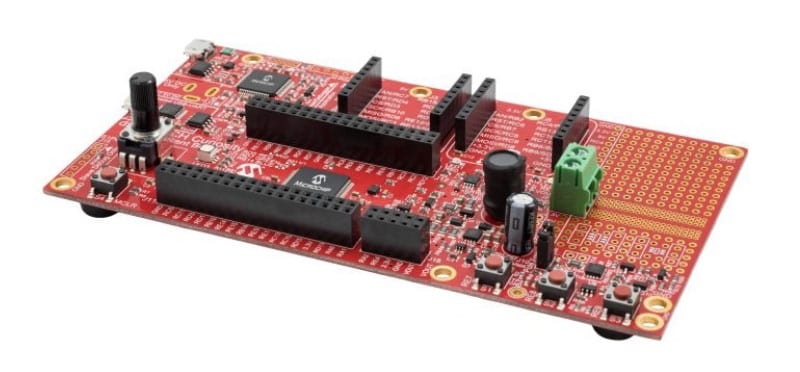
Microchip designed 16-bit digital signal controllers (DSC) such as the disPIC33 and MCUs such as the PIC24 for an array of ICE and electric vehicle (EV) powertrain applications (Figure 2). A significant benefit of this development is that these platforms provide instant response and high reliability for e-mobility in harsh operating conditions. They enable software-controlled motor control, exhaust gas recirculation (EGR) valve operation, and water and oil pump control. Sized for powertrain usage, the disPIC33 and PIC24 products also facilitate power management, battery charging, and exterior lighting controlled by the vehicle's software.
A feature that makes these components ideal for the software application is digital signal processing to increase the DSC throughput. The disPIC33 and PIC24 also boast a 16-channel pulse width modulator with precision analog/digital (both directions) converters to maximize speed and performance.
Chassis
The Arm® Cortex®-M0, M4, and M7 deliver functionality to provide software-control for on-road applications in advanced driver assist and similar partially autonomous features such as a heads-up display.
These 32-bit solutions operate at a higher voltage (5.5V) to widen their applicability range while offering industry-leading DSP performance. The Arm® Cortex® line products provide highly integrated connectivity, well suited to automotive applications. Their compact size minimizes packaging envelope consumption and lag because of excessive distance between interacting subcomponents.
Cabin and Exterior
For the most complex, innovative, and modern software-controlled car features, the Microchip 32-bit MPU is the best choice for a robust design platform. This product seamlessly handles infotainment, the human-machine interface (HMI). With processing power on par with a full computer, the 32-bit MPU analyzes the massive amount of data that the vehicle computer uses to process high memory-consuming applications and guard against cyber threats with advanced security features.
Microchip designed a product that fits this application: the Arm® Cortex®—A5-based Sama5D27, which contains a 500Hz CPU core and 128KB L2 cache. The processor, embedded media features, and innovative security features with enhanced encryption protect the data’s integrity. The Sama5D27 also contains embedded media features to enrich the user experience through its audio subsystem, 24-bit LCD interface, and 12-bit RAW camera. These features improve the accuracy of sensor data being processed through the system, which improves the accuracy of the software’s prescribed response.
Takeaway
MCUs and MPUs are already prevalent in our cars. As Evs gain more prominence, solutions such as Microchip‘s disPIC33/PIC24, Arm® Cortex®-M0, M4, and M7, and the Arm® Cortex®-A5-based Sama5D27 are posed to deliver a software-controlled reality. When designers use these components to help process the vast amount of sensor data, they can leverage existing processing infrastructure to set the stage for software-controlled cars to propel the autonomous movement. 

Rise in Automotive Electronic Controls Prompts Cybersecurity Concerns
By Steve Taranovich for Mouser Electronics
Mitigating Concerns in Today's Vehicles
Some modern vehicles have more than 100 electronic control units (ECUs). Combined with the proliferation of wired and wireless communication protocols within the vehicles, it’s obvious that automotive cybersecurity has emerged as a critical concern. In the following, we’ll examine some of the major threats against today’s vehicles and look at how Microchip mitigates security concerns with its suite of CryptoAutomotive Security ICs and other security products.

Robust Automobile Safety, Security, Reliability
Over 90 percent of accidents on the road today occur because of human errors that, in the U.S. alone, result in more than 50 million serious injuries and a cost of over $3 trillion (USD) every year. Reducing and removing the human factor from driving can significantly improve road safety. Add to this the future autonomous vehicle, which needs several components not required in today's vehicles, including real-time vehicle-to-vehicle (V2V) and vehicle-to-infrastructure (V2I) communications with various networks of different levels of trustworthiness, along with a diversity of sensors to detect driving conditions such as potholes, moisture, pedestrians, etc. What a nightmare!
For an automobile to be robust, it must have:
- Safety: Safety requirements specify that an automobile should not harm any other agent in its environment because of hazards caused by malfunctioning of electrical/electronic (E/E) components.
- Security: Security is the requirement that ensures the car’s electronic components must be resilient against system hackers.
- Reliability: This refers to the robustness of electromechanical and mechanical components and their interfaces with the E/E components of the system.
Communications inside the modern automobile have become a prime target for cyberattacks. The embedded systems in an automobile are composed of more than 100 ECUs connected by means of a controller area network (CAN). Such systems have more than 100MB of software, handling an ever-growing volume of digital information, and have highly vulnerable points, with a mix of various sensors and actuators, prime for cyberattacks, in their embedded systems. This can lead to possible dangerous automotive safety situations.

Simply adding security measures to thwart cyberattacks will not be good enough unless the automobile system timing requirements are considered. Designers must ensure that all real-time applications get executed within their deadlines and reduce the number of CAN bus transmitted messages.
The most often-used information technology (IT) configuration is a periodic activation of tasks that get executed by ECUs along with messages that are coupled with run-time priority-based scheduling transmitted by the CAN bus.
ECUs have increased in number in the automobile, but the interface channels that connect to an external environment have also grown exponentially. On the positive side, driver experience is greatly enhanced, but cyberattacks now find more opportunities to threaten vehicle safety and security.
The CAN bus can be accessed by a hacker who takes valid messages and compromises them to affect the normal operation of the vehicle. The CAN bus does not presently support security properties such as authentication and integrity of messages coming into the CAN bus. The CAN bus cannot even trace a message back to the hacker because it does not have entity authentication capability.
Such things as raising the radio volume are just nuisances to the driver and passengers, but think of the hacker remotely stopping a vehicle on the road or increasing the speed of the vehicle, which will endanger the lives of the driver and passengers.
Microchip has the first automotive cryptographic companion security IC, the TrustAnchor100 (TA100) CryptoAutomotive™ security integrated circuit that provides a means to implement security into existing systems without costly redesigns. The IC provides external Hardware Security Module (HSM) support for secure boot, CAN message authentication, Electric Vehicle (EV) battery authentication, Transport Layer Security (TLS), Wireless Power Consortium (WPC) 1.3 Qi® authentication, High-Bandwidth Digital Content Protection (HDCP) and more.
Multiple OEMs worldwide would approve the TA100 as a solution for E-safety Vehicle Intrusion Protected Applications (EVITA) Medium and EVITA Full HSM requirements.
General Security-Risk Analysis (SRA)
Designing, developing, and deploying information security methods for vehicles requires a systematic security-risk-assessment and management process throughout the vehicle’s lifecycle. A security risk analysis (SRA) should be performed with a thorough analysis of cyber threats for new automotive vehicles to achieve this.
A Cyber kill chain is the process of analyzing cyberattacks to identify threats to the organization at each stage of the attack, eliminating or mitigating the attacker’s purpose, and then planning and implementing measures that will secure the organization system.
Security Access in Automotive Diagnostic Communication
Automotive systems have experienced many documented cases of attacks in recent times. Numerous areas might also act as a stepping-stone for such attacks. Among these are the automobile controller area network (CAN), hackers using IT-based communication remotely, and attacks using servers and smartphones.
The vehicle's CAN network is a prime target to access the automobile’s diagnostic functions. Microchip TA100 provides this security with CAN Message Authorization. Vehicle diagnostic functions will write to the vehicle's internal memory and protect access to crucial functions, such as reprogramming routine processing and security access services. These are usually built into many ECUs. The problem is that this effort is not good enough by itself to keep out the creative innovations of smart hackers.
Security evaluations of ECU software update processes. However, many automaker’s ECUs contained defects in implementing their security access services, enabling brute force attacks or man-in-the-middle attacks via diagnostic tools.
Improved methods need to be implemented. As hackers get more creative, the automobile industry needs to get even more creative in defending automobile system attacks.
Microchip’s TA100 provides the following:
- Full and Partial Secure Boot
- Secure Firmware Update
- CAN Message Authentication
- WPC 1.3 Qi High-Power Transmitter Authentication
- High-Bandwidth Digital Content Protection (HDCP) Cryptographic Support
- Network Authentication and Session Establishment using TLS
- Electric Vehicle (EV) Battery Authentication
ECUs Vulnerable to Security Attacks
No longer are automobiles a fully mechanical system. They are becoming wirelessly connected computers on wheels. One major effort to combat hackers is the United Nations Economic Commission for Europe (UNECE) WP29 Working Party on Automated/Autonomous and Connected Vehicles (GRVA). This group has begun a task force on cybersecurity and software updates (CS/OTA).

This task force has developed and delivered a recommendation for integrating regulations on cybersecurity and software updates for vehicles. An ongoing test phase is in progress. Combining the TA100 and an integrated software stack will provide production-ready software for automotive Tier 1 and original equipment manufacturers (OEMs), enabling them to easily add security to any automotive module.
Vehicle manufacturers will have to ensure that suppliers and service providers implement a cybersecurity management system (CSMS). The processes have to include development, production, and post-production, and consider the monitoring of risks and threats to the vehicle and incident response processes.
Over-the Air-Update Security
To date, over-the-air (OTA) software updates for automobiles can be exploited by hackers to compromise vehicle security and safety. This issue has not yet been covered extensively enough.
The latest automobiles are quite vulnerable to cybersecurity attacks because of the computing and internet connectivity embedded within the vehicle system. The industry must protect the vehicle, driver, and passengers by implementing effective testing to detect software flaws and weaknesses. Regular updates need to be routine with critical security patches, fixes for bugs, and other needed enhancements. Just as our computers need these security measures, the latest vehicles need them even more because hacks can lead to accidents, injuries, and even deaths on the roads.
OTA software is presently the most convenient, efficient, and cost-effective means to deliver software updates—just ask Tesla Inc.
Essentially, in addition to the TA100, the automotive community needs to find/groom the most creative and talented hackers in the industry as the White Hats who will thwart the efforts of the Black Hats.
Automotive Ethernet Provides an Optimum Data Network
By Steve Taranovich for Mouser Electronics
Today's automobiles are fast becoming data centers on wheels.
Coming to the market in the near future will be features such as collision detection, lane departure warnings, and autonomous driving. These excellent safety features will need vast amounts of secure data processing, networking, and storage capabilities within the vehicle. A good example is higher data throughput necessary for advanced driver-assistance systems (ADAS) such as those found in rearview or surround-view camera systems.
The industry mantra for the next step in automotive technology is “More Bandwidth” and the Ethernet/In-Vehicle Network (IVN) will bring that capability. Ethernet connectivity will provide a high-speed communications backbone over a ubiquitous physical network in the vehicle. How will we achieve this?
In the following, we’ll explore the various single-pair Ethernet standards and explain how they work together to create an optimum automobile communication network for everything from camera video and GPS, to critical safety systems.
Single-Pair Ethernet (SPE)
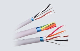
Traditional Ethernet cabling, which has been the standard for most Ethernet cables worldwide, uses two pairs of wires to transmit data. Single-pair, bi-directional, twisted, and unshielded wiring for automotive Ethernet enables parallel, high-performance transmission of data and power through Power over Data Line (PoDL) from sensors on through to the cloud.
This technology will enable lighter and lower-cost cables taking up less volume in the vehicle. Lighter cables also means improved gas mileage. Installation will also be simpler.
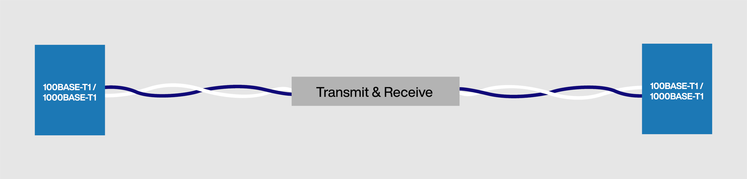
Single-Pair Ethernet technologies are standards-based technologies. The first two IEEE standards for this are 802.3bw and 802.3bp. These two standards are 100BASE-T1 and 1000BASE-TI technologies capable of 100Mbps/15m and 1Gbps/40m speed and distance limits, respectively. These standards-based technologies will easily meet future automotive needs.
These two standards are driving pioneering applications such as in-car innovations like in-vehicle communications, measurement and arbitration, diagnostics via Diagnostic Communication over Internet Protocol (DoIP), and communications between electric vehicles and charging stations. Ethernet provides the vehicle with a flexible, modular structure that is also well tailored for specific security solutions in the vehicle. Ethernet is secure over the internet as well.
Standard Ethernet vs. Automotive Ethernet
Ethernet technology is used for in-vehicle communication, measurement and calibration, and diagnostics via DoIP. This is the packaging of diagnostic messages in Ethernet frames to communicate a diagnostic tester with a vehicle. Vehicle access with DoIP is backward compatible using discretionary pins of the existing diagnostic connector. DoIP enables easy integration into various network structures, even with WLAN.
Automotive Ethernet is a different, more-demanding technology than traditional Ethernet. All automotive-grade Ethernet products will need to be AEC-Q100-qualified and support the automotive industry’s Production Part Approval Process (PPAP).
One main difference between automotive and standard Ethernet is that EMC and temperature environments are far harsher in the automobile. A higher mean time between failures (MTBF) is also needed for higher reliability in automotive technologies. Repeatability/higher MTBF and predictability are critical in the automobile for safety because failures can cause injuries and even loss of life. Safety/ASIL (ISO26262) compliance is necessary.
Hardware qualification is required in some Automotive Ethernet applications. Lower latency is usually required in the vehicle’s drivetrain for fast reactions at highway and road vehicle speeds. Validation of Electronic Control Unit (ECU) hardware and software are also required. A typical vehicle will have more than 100 ECUs that control braking, engine, transmission (drivetrain) steering, cameras, wireless communication, and more.

Present-Day In-Vehicle Technology
Various communication systems are within a typical automobile, including CAN, LIN, and FlexRay, to name a few. These systems will be in the automobile for a while longer. However, the future of automotive networking is Ethernet and especially single-pair Ethernet, which can transport data over a link 100x faster than the present CAN bus.
According to IEEE, all major original equipment manufacturers (OEMs) should have introduced the 100BASE-T1 specification for transmitting at 100Mb/s data rate over unshielded cables in production automobiles by the end of 2020. This will replace most other in-vehicle communication systems and help lower the vehicle cost.
100BASE-T1 was first introduced in series production cars in 2013, and the technology was standardized for single balanced twisted-pair cable in IEEE 802.3bw, IEEE Standard for Ethernet Amendment 1: Physical Layer Specifications and Management Parameters for 100Mb/s Operation over a Single Balanced Twisted Pair Cable (100BASE-T1), which was published in 2015. An example of a 100BASE-T1 Ethernet PHY Transceiver is LAN8770. (See the Ethernet Evaluation board EVB-LAN8770-RMII™, a plug-in card that interfaces directly with a mating Microchip host processor or controller board.)
The next-gen 1Gb/s technologies are also in automobiles today; 1000BASE-T1 (defined in 2016 in IEEE 802.3bp™, IEEE Standard for Ethernet Amendment 4: Physical Layer Specifications and Management Parameters for 1Gb/s Operation over a Single Twisted-Pair Copper Cable) and 1000BASE-RH (defined in 2017 in IEEE 802.3bv™, IEEE Standard for Ethernet Amendment 9: Physical Layer Specifications and Management Parameters for 1000Mb/s Operation Over Plastic Optical Fiber) began their first start of production (SOP) activities in 2019.
Two other new IEEE standardized spec speeds are at 10Mb/s in IEEE 802.3cg™ and 2.5/5/10 gigabits per second in IEEE 802.3ch™ and were published in 2019 and 2020, respectively. Work is underway to standardize greater than 10Gb/s (IEEE P802.3cy™ and IEEE P802.3cz™).
Competing Communication Technologies
100Mb/s and 1000Mb/s Ethernet address clear-cut speed gaps for IVN technology. New speed grades in Automotive Ethernet encounter more competition in both lower (FlexRay, various CAN variants, and A2B audio bus) and higher-speed areas (SerDes, USB, and PCIe). Usually, specialized technologies have an advantage in the beginning since they are tailored for specific-use cases and cost-optimized for those areas. Ultimately, 2.5/5/10G Base-T1 will be implemented in 2025 for ADAS and autonomous vehicles with an average of more than 100 Ethernet ports per vehicle.
Technologies developed for a single-use case can quickly become monolithic and high cost when applied to other uses. Globally standardized technologies like Ethernet grow to be augmented by a qualification ecosystem such as test houses, vendors, intelligent tools, training, and a diversified product portfolio that is critical to OEMs in areas such as risk mitigation.
Best Technology Solution for Automotive Ethernet?
The IEEE comments that "….there are clear signs of progress towards ubiquitous Automotive Ethernet." The automotive industry around the globe is thinking about a path forward for the standardized in-vehicle network (IVN) foundation and IEEE 802.3 Ethernet and P802.1DG, which are the hot topics.
All major OEMs have committed to introducing the 100BASE-T1 specification for transmitting 100Mb/s data rates over unshielded cables in series production cars by the end of the decade. 2021 is the time for global automotive decision-makers to bring the industry together and answer the difficult questions about network communications within the vehicle. Ethernet will most likely be the winner because it can offer the best solution on all software and protocol stack layers.
Solving Automotive Motor Control for EVs
By Adam Kimmel for Mouser Electronics
Automotive motor control is a principal concern in electric vehicles.
At present, premium segment EVs offer 60 to 70 motors, and this number continues to grow. The movement toward electric cars creates a myriad of opportunities for innovation. As manufacturers aim to quench the consumers’ constant thirst for connectivity, the higher amounts of functionality and automated features generate the need for an elegant and comprehensive control solution. The enhancements introduced with the 48V bus highlight the motor control challenges and the broad expertise needed to control all the vehicle motor types. Microchip offers motor-control solutions for any electric motor and acts as the singular control solution provider.

- Brushed DC (BDC): With speed and torque proportional to the applied voltage and current, brushed DC motors are a straightforward control solution. As a result, engineers select BDC for diverse applications within the vehicle.
- Brushless DC (BLDC): Like BDC in torque and speed performance, the brushless form offers a high power-to-size ratio. This property lends the BLDC to applications with distinct load conditions that are far apart. As an example, ABS engages only when the brake is depressed hard. Throttling and pumping applications rapidly change pressure from high to low. The high power-to-size ratio also improves BLDC’s efficiency.
- Stepper: While brushed and brushless DC motors focus on macro functions such as stopping the vehicle and operating pumps, stepper motors focus on precision applications such as mirror position, opening or closing the EGR valve, or regulating speed during idling. Due to requiring near-infinite control within the range, stepper motor control is defined by the motor’s construction, aiming to provide near-infinite steps for use as set points.
- Switched Reluctance (SR): Like brushless DC, SR motor applications are high-speed and power dense. Because they do not contain permanent magnets, SR motors provide efficient, high-speed action at a reduced packaging size.
Spotlight Application: 48V Bus
Current EVs are 12V systems, and they reduce carbon dioxide, carbon monoxide, nitric oxide, and particulate matter exhaust emissions substantially. Engine-driven functions must convert to electric motor control to achieve this emissions improvement.
By Ohm’s Law, 48V enables higher currents for the same resistance, providing more power for additional features. Power loss is proportional to the square of current in Joule’s Law, meaning that the 48V battery reduces resistive losses over the 12V system. This result increases the number of motor-control features engineers can include on the same bus, improving the user experience. The 48V battery’s higher power density provides efficient power, smoother acceleration, an increased capacity for electrically-powered motors, and protects packaging space for additional system controls and features.
DC motor speed is directly related to voltage and inversely proportional to current. Because 12V motors run at higher current because of Ohm’s Law, they operate at higher speeds than 48V. The higher current of 12V typically results in design engineers rating them for lighter-duty applications than 48V. Provided you do not overload the motor, you can use a 12V motor on a 48V system. It will just operate at a slower speed.
Control Methods
Motor control has some fundamental differences between electric and internal combustion vehicles. Unlike the combustion engine, which provides a constant load to the system, electric motors give only on-demand power. This difference enables electric motors to avoid introducing constant load into the system. Electric motors control speed and performance by varying the applied voltage and current, though the inefficiency associated with this approach often cannot deliver enough torque.

Some standard control opportunities include driver communication features, diagnostics, regenerative braking, and power management. These use cases encourage the control strategy to promote customization for the user by tailoring the experience to his personal preference and improving the motor’s efficiency by recovering energy from braking and managing power.
To improve control, design engineers use electronic switches to reduce voltage and current instantly. This approach still carries static resistive (IR) losses and dynamic (transition) losses through on-off cycles. The design objective for these switches is to minimize these loss mechanisms. As with the 48V bus, increasing voltage (and current in turn) can reduce loss.
Higher-voltage switches are more complex to design, providing an opportunity for innovation: silicon carbide (SiC) MOSFETs. This chemistry offers higher critical breakdown voltage, thermal conductivity, and melting point than its silicon-based predecessor, making SiC better for high-temperature applications. These improvements enable thinner material and a broader bandgap to be used, reducing conductive resistance and leakage losses. Higher temperature operation also reduces the need for cooling throughout the system, reducing overall complexity and cost.

The Microchip SiC Schottky Barrier Diode is a prime example of this switching technology. This switch provides high-temperature, low-loss performance over silicon, making it an excellent choice for the breadth of motor applications previously described. The extended usage range of this component extends the range of applicability for this switch. It demonstrates Microchip’s capacity to offer a product to address any motor control applications in a vehicle.
Against the challenge of 60 to 70 motors in a car, with applications ranging from windshield wipers to regenerative braking, Microchip offers control solutions for each of them with a single manufacturer. Addressing the breadth of motor control applications with one supply partner enables the engineer to learn tools and networks for multiple suppliers. They can be confident that the various motor controls will communicate while optimizing system performance given Microchip’s expertise in all motor-control areas.
With both control and drive stages for motor control, Microchip can cover existing and forthcoming controls challenges. As evidenced in the 48V bus application, adopting a control strategy for higher-voltage operation improves performance, wastes less energy, and creates a better user experience overall.
How Digital Control and SiC Microchips Unlock Level 3 Fast Charging
By Adam Kimmel for Mouser Electronics
The success of the Tesla Model 3 has disrupted the global automotive market.
With industry experts betting it would fail, the Model 3 launch hit a home run in both the US and Europe, catching the EU off guard. With its success, GM, Ford, and Volkswagen have entered the arena, committing $20 billion, $11 billion, and $91 billion (respectively) to deliver a comprehensive electric portfolio by 2030. With these announcements, coupled with aggressively tightening global emissions standards and public pressure to remove atmospheric carbon, EVs are finally into the mainstream.
Though electrification has taken a big step forward, to gain real commercial momentum, the experience of owning and operating an EV needs to be at or better than current combustion engine models. Battery charging has been a critical limit for mass adoption, with a developing charging infrastructure and long average charge times limiting who can fit an EV into their current lifestyle. Reducing charge time is one of the biggest remaining hurdles for electric vehicles to overtake traditional cars in global sales. Combining digital control and silicon carbide (SiC) delivers level 3 or DC fast charging to reduce these charge times dramatically.
Charging Levels and Definitions
The automotive industry categorizes electric vehicle charging into three levels, numbered 1 to 3. The higher the level, the faster the charge. Engineers' development on charging technology has shifted charge times from hours to minutes and removed the practical reality that the vehicle must charge overnight. The three charging levels are described below, with their ranges and performance.

Level 1 (120V AC)
It is possible to charge an electric vehicle with a standard 120V AC home outlet. This charging method only adds about 40 miles of range in 8 hours due to the low voltage level. Even a full overnight charge will not be sufficient to replenish an empty battery. Due to this method’s impracticality, only 5% of public EV charging stations employed Level 1 technology.
Level 2 (208V/240V AC)
As the charge time goes down, the voltage goes up. Level 2 AC charging operates at 240V for residential or 208V for commercial properties. Though most homes have 240V power, the user may need to upgrade or move some equipment to enable the vehicle to access the power. This level provides 10-20 miles of range per hour of charge. Though four times level 1’s output, this level is still a long-term time investment. At-work charging applications commonly use level 2 charging, where the vehicle owner can get up to half the range a traditional vehicle delivers (160 miles) over the course of a workday.
Level 2 is a step-change improvement over level 1, but it requires a dedicated 40A circuit. The convenience of still charging at home or the office and the performance gain over level 1 are two reasons over 80% of public charging stations employ this technology.
Level 3/DC Fast Charge (208V/480V AC)
DC fast charging begins to approach parity in refueling (recharging) time between combustion and electric vehicles. The power conversion from AC to DC occurs within the charging station, followed by a DC/DC step that converts the voltage to the level the EV requires. It is the high-voltage DC power that reduces the time to charge.

Achieving this level means that drivers can refuel mid-trip and that charging stations can replace gas pumps to add convenience for operators. Enabling charging while away from home also means that drivers may not need to upgrade their home equipment, just as traditional combustion-engine cars have to refuel at dedicated stations. This EV charging technique delivers up to 80 miles of range in 20 minutes – 12 times the rate of level 2.
Achieving level 3 charging requires an innovative solution, which is why at the moment, it accounts for only 15% of the existing public charging infrastructure. The chargers must be small, durable, reliable, and efficient to ensure commercial viability for widespread use. Digitally controlled silicon carbide (SiC) semiconductors solve the technical challenge and clear the path for reducing EV charge time to the level of a gas-powered car.
The Solution to Deliver DC Fast Charge
The approach takes a three-phase power source and employs a Vienna rectifier-based power correction factor. It adds the DC-DC converter to provide the target voltage for the vehicle. The process contains switching losses due to switching frequencies at a high-power multiple and conversion loss escaping as heat. To reduce these inefficiencies and enable higher-temperature operation, engineers developed wide bandgap semiconductor materials, such as SiC.
Silicon Carbide (SiC)
Microchip's MOSFET-SiC-1200V is a leading example of transformative SiC technology (Figure 2). The product offers high performance for improved system efficiency and reduced weight and size. The 1200V does not degrade over its life and delivers fast switching enabled by its wide-bandgap through reduced internal gauge resistance with providing stable, reliable operation.
With less resistance and heat loss characteristics, SiCs are power-dense. They package efficiently and do not contain excess material, making them lighter and more durable due to higher-temperature operation. Silicon carbide is bidirectional, easier for designers to achieve in SiC than silicon, and provides the efficiency, power density, reliability, and durability that DC fast charging requires. SiC addresses the technical challenges of high-voltage charging both efficiently and economically.
Digital Control
Applying digital control to the SiC is the second critical aspect of delivering level 3 charge. A solution like the AgileSwitch® High-Performance Gate Driver Core matches the performance level of the SiC with the robustness of digital control. This controller optimizes the inter-step switching for efficiency and employs circuit control protection to address the technical challenges of higher-voltage, elevated-temperature operation for EV level 3 charging.
Takeaways
Electrification is a direction, not a distraction. Major automotive players are joining Tesla in bringing electric vehicles into the mainstream and are pushing for cost-competitiveness to combustion-engine cars. Once there is a critical mass of EVs on the road, charge time may become a limiting factor to delivering the overall experience consumers expect.
Level 3 charging is a step-change in enabling drivers to charge their vehicles on the go. Though still above the time it takes to refuel a gasoline vehicle, the advancements, and technology needed for level 3 move the industry down the path to level 4 charging, which would provide a sub-5 minute charge. Due to the high voltage requirements and subsequent temperature rise, SiC coupled with digital control provides the ideal solution to deliver level 3 charging. This combination offers the performance, durability, and reliability the application requires and balances it with an efficient, economic, and safe control methodology.
Photo/imagery credits (in order of display)
RSVector - shutterstock.com, elenabsl - stock.adobe.com