


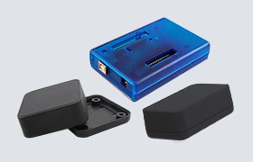


Texas Instruments LM25148B-Q1EVM2100 Evaluation Module (EVM)
Texas Instruments LM25148B-Q1EVM2100 Evaluation Module (EVM) is designed to use a regulated or non-regulated high-voltage input rail ranging from 5.5V to 36V to produce a tightly regulated output voltage of 5V at load currents up to 10A. This wide VIN range DC/DC design offers an outsized voltage rating and operating margin to withstand supply rail voltage transients.
The free-running switching frequency is 2.1MHz and can be synchronized to an external clock signal at a higher or lower frequency. The powertrain passive components selected for the Texas Instruments LM25148B-Q1EVM2100, including buck inductors and ceramic input and output capacitors, are automotive AEC-Q200 rated and available from multiple component vendors.
Features
- Wide input voltage operating range of 5.5V to 36V
- 1% accurate fixed 5V output
- Switching frequency of 2.1MHz externally able to be synchronized up or down by 20%
- Full-load efficiency of 93.3% at VIN = 12V
- 9.9µA typical controller standby current at VIN = 12V
- Optimized for ultra-low Electromagnetic Interference (EMI) with dual-random spread spectrum and active EMI filtering
- Peak current-mode control architecture provides fast line and load transient response
- Integrated slope compensation adaptive with switching frequency
- Forced PWM (FPWM) or pulsed-frequency modulation (PFM) operation
- Optional internal or external loop compensation
- Integrated high-side and low-side power MOSFET gate drivers
- 2.2A and 3.2A sink and source gate drive current capability
- 20ns adaptive dead-time control reduces power dissipation and MOSFET temperature rise
- Overcurrent protection (OCP) with hiccup mode for sustained overload conditions
- SYNC OUT signal 180° out-of-phase with internal clock
- Power-Good signal with open drain
- Internal 3ms soft start
- Fully assembled, tested, and proven PCB layout with 83mm × 43mm total footprint
Applications
- High-current automotive electronic systems
- ADAS and body electronics
- Infotainment systems and instrument clusters
- Automotive HEV/EV powertrain systems
Required Equipment
- Voltage Source - Use an input voltage source capable of supplying 0V to 42V and 12A
- Multimeters
- Voltmeter 1
- Input voltage at VIN+ to VIN–
- Set the voltmeter to an input impedance of 100MΩ
- Voltmeter 2
- Output voltage at VOUT to GND
- Set the voltmeter to an input impedance of 100MΩ
- Ammeter 1
- Measure the input current
- Set the ammeter to 1-second aperture time
- Ammeter 2
- Measure the output current
- Set the ammeter to 1-second aperture time
- Voltmeter 1
- Electronic Load
- The load must be an electronic constant-resistance (CR) or constant-current (CC) mode load capable of 0ADC to 10ADC at 12V
- For a no-load input current measurement, disconnect the electronic load, as the load can draw a small residual current
- Oscilloscope
- With the scope set to 20MHz bandwidth and AC coupling, measure the output voltage ripple directly across an output capacitor with a short ground lead normally provided with the scope probe
- Place the oscilloscope probe tip on the positive terminal of the output capacitor, holding the ground barrel of the probe through the ground lead to the negative terminal of the capacitor
- TI does not recommend using a long-leaded ground connection because this can induce additional noise given a large ground loop
- To measure other waveforms, adjust the oscilloscope as needed
Test Setup
")
Published: 2024-12-13
| Updated: 2024-12-16